Magnetic Calculations
About Rules of Thumb and Quick Calculations
How do I determine the magnetic flux density at a particular distance away from a magnet?
What is the "working l/d ratio" for various magnet materials?
What is the holding force of a magnet?
How are energy product and magnet strength related?
Magnet strength needs to be defined. Magnet strength actually is a measure of total flux in the area of interest. If greater holding strength is desired, then more Br is needed, and since holding force is proportional to B^2, the improvement will be proportional to the ratio of Br's squared. In a spectrometer application, charged particle deflection will be directly proportional to the Br increase. If resistance to demagnetization is the reason for wanting "greater strength", then a magnet with a higher Hci value is needed. Even if the high Hci magnet shows lower open circuit flux density, it could provide more under operating conditions.How do I determine the magnetic flux density at a particular distance away from a magnet?
To calculate simple field values, you can use the calculators available in the Resource Center of our website.What is the "working l/d ratio" for various magnet materials?
"Working l/d ratios" are those which produce a load line through the Bd/Hd values associated with the maximum energy product. Typically you would want to use a l/d ratio somewhat higher (in the final circuit) to protect against unplanned demagnetization effects.
As a rule of thumb, the "equivalent" Length/Diameter ratio for an isolated magnet should be (0.5 * Br) / Hc, or more. That would give an Alnico 5 magnet length/diameter ratio of 10, while ceramic or rare earth would operate with a 0.5 ratio. A high performance coefficient is especially important for Alnico 5 because of its low coervicity and the pronounced "knee" in its second quadrant demag curve. Its low resistance to demagnetization makes Alnico susceptible to demagnetization due to shock, heat or magnetic fields from adjacent magnets.
It should be emphasized that the working performance coefficient is the prime concern; the value achieved when the magnet is placed in the final circuit. Open circuit performance coefficients are only important if the magnet operates by itself, or the value is so low that irreversible flux losses are likely before the magnet is placed into the magnetic circuit. In the latter case, magnetization after assembly would be advised.What is the holding force of a magnet?
Force is calculated by
F = 0.577 * B^2 * A
where B is the flux density in the gap in kG, and A is the magnet area in square inches.
For round or rectangles shapes, use current sheet calculations to estimate B in the gap, or at the end of the magnet. These equations are available in under the Tools section of the navigation bar on our Web site. They can also be found in our Reference and Design Manual, available for download under our Engineering Support section.
If the magnet is in contact with steel, double the magnet length since the steel will mirror the magnet's properties. For round or rectangles some distance off a steel keeper, use current sheet equations to calculate flux at half the separation distance. This is a ballpark calculation and empirical values are usually higher.
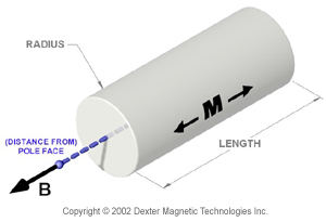
Field on Axis of a Cylindrical Magnet Calculator
Calculates the field strength on the axis of an axially magnetized cylindrical magnet.
Fill in all of the black-outlined boxes and the results will appear in the light-gray boxes. Units may be selected as either CGS (Gauss, in.) or SI (mTesla, mm). The required geometrical inputs are defined in the diagram. This calculation works best with magnetic materials displaying "straight line" demagnetization curves.
Residual Induction (Br) data is on our magnet material pages.
Magnetic Field Calculators
Below are various magnetic field calculators and calculations intended to be a resource for you when specifying your magnet design. Click on the calculation name to be directed to the specific interactive magnetic field calculator page.
Field Calculations for a Rectangle
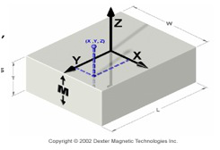
Calculates the field strength of a rectangular magnet at any given X, Y, and Z Position
Fill in all of the black-outlined boxes and the results will appear in the light-gray boxes. Units may be selected as either CGS (Gauss, in.) or SI (mTesla, mm). The required geometrical inputs are defined in the diagram. The origin is located at the center of the pole face. The X, Y, and Z positions of interest are relative to this origin. This calculation works best with magnetic materials displaying "straight line" demagnetization curves.
Field on Axis of a Ring Magnet
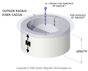
Calculates the field strength on the axis of an axially magnetized ring magnet.
Fill in all of the black-outlined boxes and the results will appear in the light-gray boxes. Units may be selected as either CGS (Gauss, in.) or SI (mTesla, mm). The required geometrical inputs are defined in the diagram. Negative values of "d" calculate the axial field strength below the top surface of the ring magnet. This calculation works best with magnetic materials displaying "straight line" demagnetization curves.
Residual Induction (Br) data is on our magnet material pages.
*Note: The distance from top surface of magnet (d) should be positive.
Pull Strength on Steel for a Rectangle
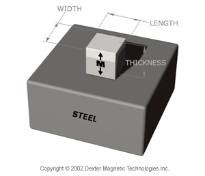
This calculation estimates the pull strength on steel for a rectangle.
Note that effective magnetic length is two times actual length for straight line materials in contact with steel, thus the permeance coefficient increases when in contact.
Residual Induction (Br) data is on our magnet material pages.
Pull Strength on Steel for a Cylinder
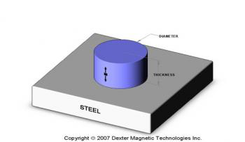
This calculation estimates the pull strength on steel for a cylinder.
Note that effective magnetic length is two times actual length for straight line materials in contact with steel, thus the permeance coefficient increases when in contact. Note that the poles of Alnico magnets are not at the magnet ends except when magnetized in a closed circuit. When removed from the magnetizing yoke, the poles move inward and the poles will never return to the end when placed on steel.
Residual Induction (Br) data is on our magnet material pages.
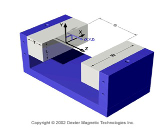
Field Calculations for a Permanent Magnet Dipole
Calculates the field strength for a Steel Dipole
For a dipole, the field within the airgap may be calculated by assuming that the steel yoke has the effect of double the magnetic length of the magnet volume - the field through the airgap volume can then be determined to within respectable limits (+/- 5% or so). Better results are achieved with rare earth materials. Enter the length of the Air gap (G) along the z-axis, together with the X, Y and Z Coordinates.
Residual Induction (Br) data is on our magnet material pages.
Field on Axis of a Cylindrical Magnet Calculator
Calculates the field strength on the axis of an axially magnetized cylindrical magnet.
Fill in all of the black-outlined boxes and the results will appear in the light-gray boxes. Units may be selected as either CGS (Gauss, in.) or SI (mTesla, mm). The required geometrical inputs are defined in the diagram. This calculation works best with magnetic materials displaying "straight line" demagnetization curves.
Residual Induction (Br) data is on our magnet material pages.
In the previous:没有了!
The next article :没有了!
